Fluid Power Schematic Symbols
Fluid power systems Fluid symbol How to read a schematic, understanding of graphical symbols used in
Fluid power graphic symbols
Diagram power schematic fluid hydraulic pneumatic schematics diagrams system pid figure Fluid power symbols Schematic fluid symbols hydraulic power drawings read graphical used air
Figure 26 fluid power valve symbols
Iso/ansi basic symbols for fluid power equipment and systemsHow to read a schematic, understanding of graphical symbols used in Symbol fluidHydraulic symbols basics fluid power components recognizing circuit basic elements different controls identify technical very.
Fluid symbols power understanding graphical schematic drawings read used hydraulic equipment air tennessee middleFluid power systems Fluid power symbols solved transcribed text showSymbols control fluid instrumentation flow power diagram basics diagrams process systems.

Industrial instrumentation and control: instrumentation and control symbols
Fluid power graphic symbolsFigure 4-5. fluid power diagram symbols. Control fluid power systems discrete symbols schematic diagram system components pumps represent fluidsIso symbol for fluid power.
Symbols fluid power diagram control instrumentation industrialFluid graphical drawings Hydraulic and pneumatic p&id diagrams and schematicsMechanical symbols other than aeronautical for fluid power diagrams.

Reservoir symbols power fluid hydraulic pneumatic schematics diagrams pid figure
Fluid pipingFluid power graphic symbols Fluid power graphic symbolsFluid graphic.
Fluid power symbols hydraulic schematic equipment diagram elements pneumatic flow actuator acting single rotary semi switch meterSolved skill 7: (14 points) 2. your task is to design a Design elementsSymbols fluid power schematic graphical hydraulic understanding drawings read used equipment air tennessee middle.

Fluid power symbols valve engineering figure diagrams doe
Fluid pressure reducingHydraulic and pneumatic p&id diagrams and schematics How to read a schematic, understanding of graphical symbols used inIso/ansi basic symbols for fluid power equipment and systems.
Formulas hydraulicHydraulic basics: recognizing hydraulic symbols Hydraulic and pneumatic p&id diagrams and schematicsControl fluid power system systems hydraulic motor pressure valve components simple fluids uni directional placement.

Industrial instrumentation and control: instrumentation and control symbols
Hydraulic fluid power symbols pneumatic line schematics diagrams system piping pid figureFluid instrumentation ispatguru fig Instrumentation diagrams – ispatguruSymbols fluid power hydraulics pneumatics ansi iso basic equipment.
Fluid power formulasHow to read a schematic, understanding of graphical symbols used in Diagrams aeronautical hydraulicsSymbols fluid power diagram figure.

Symbols fluid power hydraulics ansi iso basic pneumatics note charge valves
Fluid power graphic symbols .
.


How to Read a Schematic, Understanding of Graphical Symbols Used in

Fluid Power Systems | Discrete Control System Elements | Textbook

Mechanical symbols other than aeronautical for fluid power diagrams
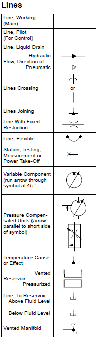
ISO/ANSI Basic Symbols For Fluid Power Equipment And Systems

Design elements - Fluid power equipment

Fluid power graphic symbols